Hardware
Brief
Sentry2 is a vision sensor which is designed by K210 - an advanced 64-bits RISC-V neural network processor. This device integrates a variety of advanced vision algorithms, which can meet the basic vision processing needs. The on-board ESP8285-WiFi chip can be programmed in Arduino IDE to realize online-recognition, image transmission, AIoT and other applications. ESP8285 can be used as a controller for K210 which is help for AI programming without external controller.
We offer 2 editions: Enterprise Edition (marked E) and Consumer Edition (marked C).
Applications: Robots, Smart Cars, Creative Design, STEAM Education, Maker, Toys, AIoT

LED: Represents different detection states.
Camera: Capture image data. User can adjust the image zoom, white balance, brightness, saturation and other parameters for camera.
WiFi Antenna: An ESP8285 Wifi Chip can realize online-recognition, image transmission, AIoT applications.
K210 Processor: A powerful MCU with a neural network processing unit, dual-core 64-bits RISC-V processor.
SD Slot: Support Micro-SD(TF) card for image storage (Note:Not all the types of SD card are supported, SPI communication only)
USB: The onboard USB-UART chip can directly communicate and control with the computer, and firmware update. (CAUTION:the USB power supply will be output through the 4pin communication port, DO NOT powered at the same time)
LCD Screen: TFT-ISP color screen with high definition and wide view brings small and excellent image display effect
Joystick: For UI interaction which support 5 directions control (up, down, left, right, enter)
Reset button: Restart the hardware
Output Port: A 4-pins output port for communication, support UART and I2C mode
Hardware Parameters
Item |
Unit |
Enterprise |
Consumer |
Note |
|---|---|---|---|---|
Voltage |
V |
3.3~5.0 |
3.3~5.0 |
DO NOT powered by USB and Output Port at the same time |
Current |
mA |
190 |
150 |
5V supply and running Face vision |
Size |
mm |
40×32×12 |
40x32x12.5 |
without shell |
Weight |
g |
15 |
15 |
without shell |
Mounting Hole Spacing |
mm |
32 |
32 |
|
Mounting Hole Diameter |
mm |
3 |
3 |
|
Camera Type |
NA |
CMOS |
CMOS |
|
Camera Resolution |
pixel |
500W |
200W |
|
Camera FPS |
fps |
50 |
25 |
|
Camera FOV |
degree° |
70 |
68 |
|
Screen Type |
NA |
TFT-ISP LCD |
TFT-ISP LCD |
|
Screen Size |
inch |
1.3 |
1.3 |
|
Screen Resolution |
pixel |
240×240 |
240x240 |
Vision List
Details: Vision
Vision ID |
Name |
Enterprise |
Consumer |
Brief |
|---|---|---|---|---|
1 |
Support |
Support |
Return the R(red),G(green),B(blue) value and its label of each region. Up to 25 regions |
|
2 |
Support |
Support |
Detect a specified color block. It supports black, white, red, green, blue and yellow color blocks setection at the same time |
|
3 |
Support |
Support |
Support 16H5, 25H9, 36H11 Apriltag family. Up to 25 tags |
|
4 |
Support |
Support |
Find lines and return its endpoints and degrees, support 1-5 lines |
|
5 |
Support(25 model data) |
Support(15 model data) |
Training objects and categorize them. Up to 25 model data |
|
6 |
Support(traffic, shape, number) |
Support(traffic) |
Identify special card patterns, including 10 traffic cards, 9 shape cards, and 10 number cards |
|
7 |
Support(25 modeldata) |
Support(15 model data) |
Face detection and recognition, support mask detection, can store 25 model data |
|
8 |
Support |
Support |
Classify 20 common objects, such as cat, car, human etc |
|
9 |
Support |
Not Support |
Recognition a simple QR code |
|
10 |
Support |
Support |
Running custom algorithms which is running in the ESP8285-WiFi chip on board |
|
11 |
Support |
Not Support |
Determine if there are moving areas in the image |
Platform and Library
Platform |
Language |
Controller |
Driver and Library |
|---|---|---|---|
C/C++ |
Arduino |
||
Graphical |
Micro:bit |
||
Graphical,C/C++,MicroPython |
Arduino、Micro:bit |
||
Graphical |
Arduino |
||
MicroPython |
Micro:bit |
||
ARM PC |
C/C++ |
Raspberry Pie,Linux |
How to Use
Sentry2 can be connected to a controller via the output port, or connect to computer by a USB cable. The output port can be set as UART mode or I2C mode, device address and baudrate can also be modified.
Drivers, firmware, manuals, third-party resources: download
CAUTION:USB and Communication Port can NOT be powered at the same time !!!
Connect the Controller
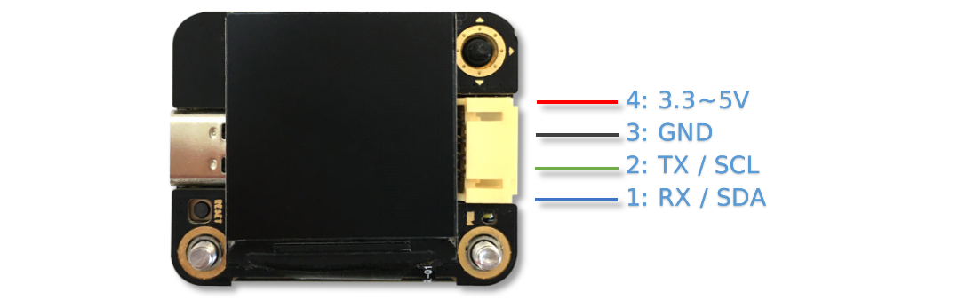
Output Port Pins Definition
Pins |
UART Mode |
I2C Mode |
Note |
|---|---|---|---|
1 |
RX |
SDA |
|
2 |
TX |
SCL |
|
3 |
GND |
GND |
|
4 |
VCC |
VCC |
CAUTION!! When the USB is inserted, this port can supply power to external devices. This port cannot be directly connected to battery. When the USB is inserted, it cannot access the 3.3V system |
Connection
Take Arduino UNO as an example
UART Mode
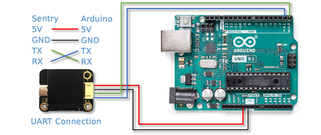
NOTE: In UART Mode, make sure your connection is correct: Sentry2 RX - Arduino TX, Sentry2 TX - Arduino RX
NOTE: If you want use the soft-serial port, you can specify other I/O ports. For details, see SoftSerialExample in Arduino
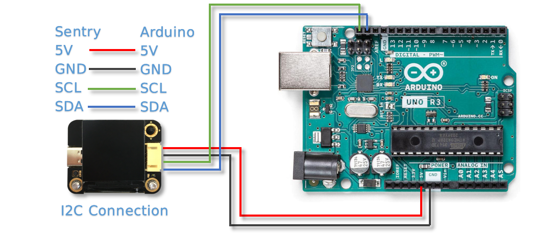
NOTE: Because the RX and TX pins of Arduino UNO share ports with the firmware uploading, it is necessary to disconnect the RX and TX connections during the program uploading, we suggest to use I2C mode or soft-serial ports for UNO
I2C Mode
UI - User Interface
Sentry2 has 2 types of UI pages: Running page and Setting page
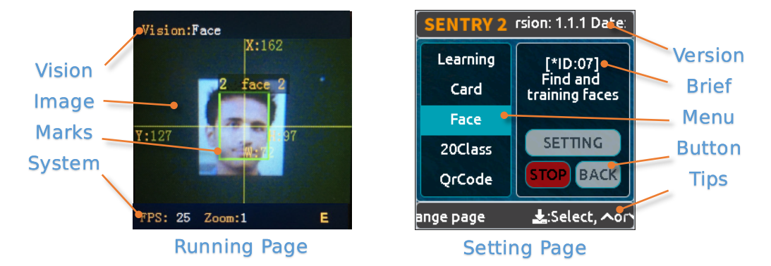
Running Page
Vision Status: This area displays the current vision name
Image: Display images from the camera
Marks: Mark the detected objects, such as detection box, coordinates or informations
System Status: Camera frame rate, zoom level or wifi status
Setting Page
Menus: Click the joystick up or down to select menus, and vertical click to enter
Version: The firmware version and date
Brief: Describes the current menu
Buttons: Interactive buttons. The button will be highlighted blue edges if it has been selected
Tips: Display some tips for operation
UI Setting Page

In the running page, you can right click the joystick to enter the UI setting page. There are 3 pages: vision setting, camera setting, and hardware setting
If you click the joystick to the left, you will exit the current page one by one until you return to the running page
Vision Setting: Enable or Disable visions and parameters setting
Camera Setting: You can set the camera zoom, white balance, saturation or other camera settings
Hardware Setting: Set the output mode, uart baudrate, device address, light color, language and other hardware configurations
Hardware Setting
Joystick Operation
Current Page |
Operation |
Brief |
|---|---|---|
Running |
Up Click |
Switch the last vision |
Running |
Down Click |
Switch the next vision |
Running |
Left Click |
Snapshot(When SD card is inserted) |
Running |
Right Click |
Enter setting page |
Running |
Vertical Click |
Training models (for special visions) |
Running |
Upward Long Press |
Camera zoom in |
Running |
Downward Long Press |
Camera zoom out |
Running |
Leftward Long Press |
Turn On/Off LCD Screen |
Running |
Vertical Long Press |
Delete all models (for special visions) |
… |
||
Setting |
Up Click |
Switch the previous menu or button |
Setting |
Down Click |
Switch the next menu or button |
Setting |
Left Click |
Switch the previous setting page / back to running page |
Setting |
Right Click |
Switch the next setting page |
Setting |
Vertical Click |
Select |
… |
||
Startup |
Upward Press > 10 seconds |
Restore the hardware default setting |
Startup |
Vertical Click |
Enter K210 firmware upgrading mode |
Startup |
Downward Long Press |
Enter ESP8285 firmware upgrading mode |
NOTE: Click is short press, Long Press must be hold the button at least 2 seconds before release
Output Setting
Some output configurations can be set if you want use a controller to communicate to Sentry2.
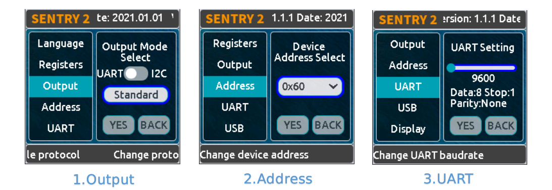
On the running page, right click the joystick 3 times to enter the hardware setting page
On the “Output” option, vertical click the joystick to enter the settings
Select “UART” or “I2C” mode. Generally, I2C mode is faster which is conducive to improving the frame rate of image processing if your controller cannot support high baudrate UART mode.
Choose the “Standard Protocol” or “Simple Protocol” for UART mode. Generally, select “Standard Protocol” if you want use the driver library.
Click ”YES“ and return
Select the “Address” option from the left menus
Set the Sentry2 hardware address, “0x60 ~ 0x63”, click “YES” and return. Default is: 0x60
Enter the “UART” setting page if you select the UART mode
- Move the slider left or right to set the uart baudrate: “9600, 19200, 38400, 57600, 115200, 921600, 1152000, 2000000”
The higher baudrate can take shorter time for data transfer which can improve the image frame rate. You need to check the max baudrate of your controller can be supported. When the communication is abnormal, you should reduce the baudrate
Left click the joystick 3 times to return to the running page
USB Setting
Sentry2 can be communication with the computer by a USB-C cable. Its baudrate can be set separately. USB mode is based on “Standard protocol” or “Simple Protocol” too.

Baudrate:Support “9600、19200、38400、57600、115200、921600、1152000、2000000” baudrate. USB can be disabled if the slider is on the left
to UART:Enable or Disable the data transmission between USB and UART
Tip: If the sent data match to the instructions of the Protocol, the instructions will be executed instead of through output
Display Setting
The detection results can be marked when the vision is running. There are 3 marks: detection Box, coordinates X-Y and informations
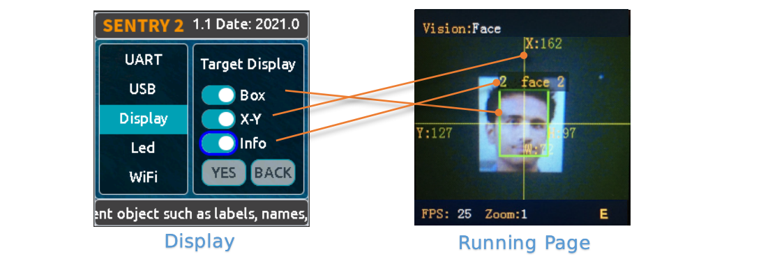
Box: A rectangular box showing the detected objects
X-Y: Draw the horizontal and vertical coordinate lines for the detected object, and displays, X: horizontal position, Y: vertical position, W: object width, H: object height
Info: Displays information about the object, such as its classification label and name
*Tip: When carrying out multi-result detection, drawing too many marks may reduce the frame rate, you can properly turn off some marks *
*Tip: Some vision do not have all the drawing elements, such as “Line detection” does not draw coordinate lines *
LED Setting
There 2 LEDs in front of the hardware can indicate the detection status. The led color will be changed due to the detection results for each frame
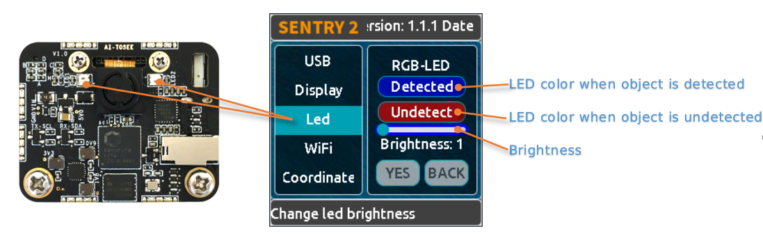
User can set the LED color for “detected” state or “undetected” state respectively. Click the joystick to change the color by the follows sequence:

Black color means the LED is turned off
When the “Detected” and “Undetected” colors are the same, the LEDs will keep lighting
The “Brightness” range from 0 to 15, where 0 means turn off the light and 15 is the brightest. Generally, set the brightness to 1 or 2
- Turn Off the LED
In some cases, led should be turn off, otherwise, its lighting may cause interference to the image recognition (such as Color or Blob vision). There are two ways to turn off the LED:
Set “Detected” and “Undetected” to black
or
Set “Brightness” to 0
- Fill Light
When the environment is dark or in a backlight environment, you need to fill light:
Set “Detected” and “Undetected” to white
Set “Brightness” to 15
WiFi Setting
The on-board ESP8285-wifi chip of the Sentry2 can be communicated to the K210 chip through an internal UART port. When “Custom Vision” is enabled, the ESP8285 chip will working.

Baudrate: Support “9600、74880、115200、921600、1152000、2000000、3000000、4000000” baudrate, WiFi can be disabled if the slider is on the left
to UART:Enable or Disable the data transmission between WiFi and UART
to USB:Enable or Disable the data transmission between WiFi and USB
Tip: If the sent data match to the instructions of the Protocol, the instructions will be executed instead of through output
Coordinate Setting
Sentry2 supports 2 coordinate systems: Absolute and Percentage
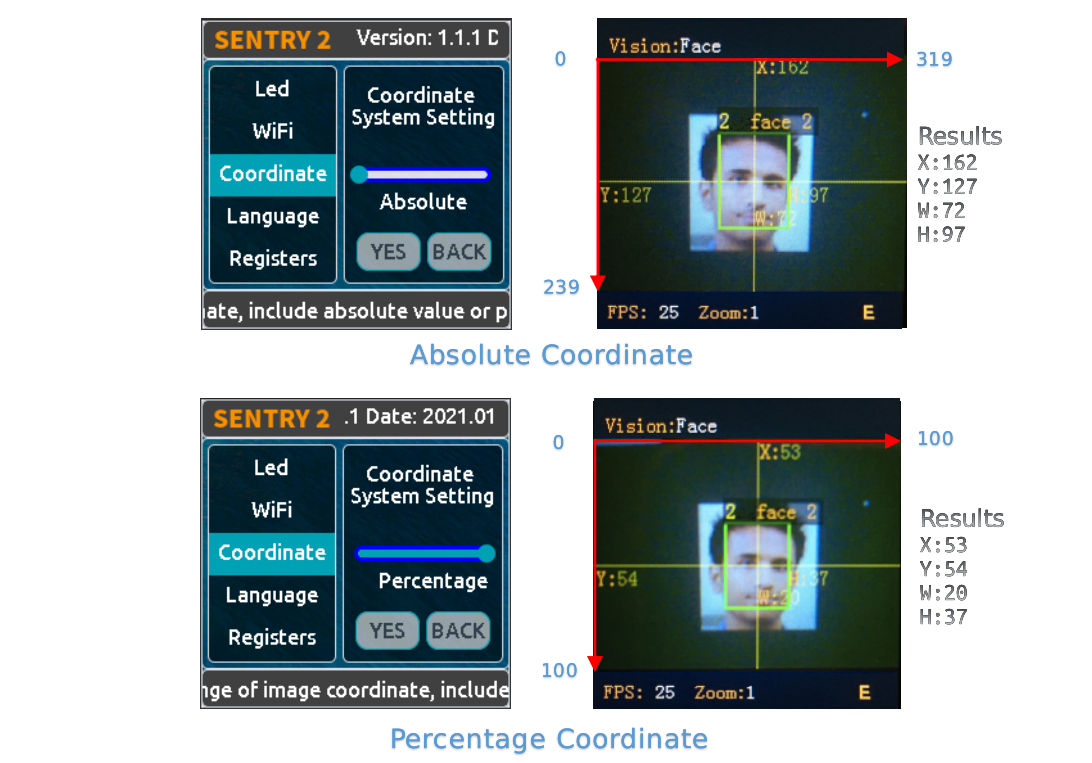
Absolute: In this mode, the actual coordinate results are returned. Range from “0 to 319” (horizontal) and “0 to 239” (vertical). The center point is (160,120). This mode has higher accuracy.
Percentage: In this mode, the actual coordinate results are quantified to the range of “0 ~ 100”. Both range in horizontal and vertical direction are from “0 to 100”. The center point is (50,50).
Language Setting
You can change the system languages: English or Chinese.

Registers Setting
Sentry2 registers operations: Auto Save Mode, Save Register, Default Settings

Auto Save: Some registers value will be automatically saved if this mode is enabled, otherwise, registers will reset to the default value after the next startup. Generally, this mode should be disabled.
Save REG: Save the current register values
Default: Restore registers to factory settings. Click this button firstly and then click “YES”
Camera Setting
Digital Zoom
You can zoom in the camera for the objects in the distance, support 1 to 5 levels of adjustment
Increasing the zoom will make the object larger, but the field of view will be smaller and you will see less
Reducing the zoom will make the object smaller, but the field of view will be larger, allowing you to see more
You also can change the zoom by joystick: Zoom in - upward long press or Zoom out - downward long press
AWB - Auto White Balance
Different light environment (white light or yellow light) may cause white color unbalanced. It is necessary to adjust the white balance. There are four modes: Auto, Locked, White and Yellow
Auto: This mode is the default mode and applies to most environment
Lock: When there is a large area of monochromatic background in the image, white is unbalanced which will lead to color recognition errors. Therefore, it is necessary to lock the white balance before recognition to avoid automatic color adjustment. The method is as follows:
Face the camera to a white paper and keep a distance of about 20cm
Enter “AWB” menu and select “Lock” mode
Click “YES”
Return to running page
White: Use in white light environment
Yellow: Use in yellow light environment
Saturation
Increasing the saturation will make the color become bright, color will be strengthened and prominent
Decreasing the saturation will dull the color, and at very low levels it will look like black and white
Brightness
You can change the brightness of the image if necessary
Contrast
Increasing contrast will make the difference between neighboring places with color difference higher
Reducing the contrast will make the image look dull
AEC - Auto Exposure Control
The light intensity can reduce the exposure value when the image is exposed
On the contrary, if the environment is dark, you can increase the exposure value
Rotate
The image will rotate 180 degrees if this is enabled
Vision Running
There are several ways to Enable/Disable vision: from UI page, click joystick, or by controller commands
By UI Settings
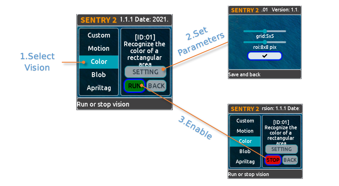
Select the vision from the left menus of the Vision setting page
Some visions can be configured, click “Setting” to enter
If the red “Stop” button is displayed at the lower left of the right control area, it means that the algorithm is currently closed. After clicking it, it will change to a green “run” button, which means that the algorithm is started. Click it again and it will change to the red “Stop” button again.
By Joystick
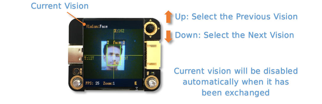
Short click the joystick up and down to enable or disable a vision. The previous vision will be closed if new vision is running
Vision switchover sequence is sorted by Vision-ID
By Commands
In this way, controller needs to read and write registers to enable or disable the vision. We provide the driver libraries for different programming platforms
In UART mode, register reading or writing must according to Standard Protocol or Simple Protocol. For details, see the related sections
I2C mode can directly read or write registers
Enable vision:
Write Vision ID to register 0x20-VISION_ID
Write 0x01 to register 0x21-VISIO_CONF1 to enable vision, otherwise, write 0x00 to disable
For details, see the registers
Vision Result
Results on The Screen
The target object will be marked on the screen when it is detected. The meanings of marks:

Result by Commands
Results can be read out by the controller.
Read results:
Write vision id to register 0x20-VISION_ID
Read register 0x34-RESULT_NUM to get how many objects are detected
Write the result id, which you want to read, to register 0x24-RESULT_ID
Read results by registers 0x80~0x89
Address
Name
Brief
0x80
RESULT_DATA1_H8
Result 1, Hight 8 bits
0x81
RESULT_DATA1_L8
Result 1, Low 8 bits
0x82
RESULT_DATA2_H8
Result 2, Hight 8 bits
0x83
RESULT_DATA2_L8
Result 2, Low 8 bits
0x84
RESULT_DATA3_H8
Result 3, Hight 8 bits
0x85
RESULT_DATA3_L8
Result 3, Low 8 bits
0x86
RESULT_DATA4_H8
Result 4, Hight 8 bits
0x87
RESULT_DATA4_L8
Result 4, Low 8 bits
0x88
RESULT_DATA5_H8
Result 5, Hight 8 bits
0x89
RESULT_DATA5_L8
Result 5, Low 8 bits
For details, see the registers
Protocol
Details Protocol chapter
Registers
Please contact us
Support:support@aitosee.com
Sales:sales@aitosee.com